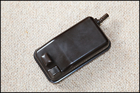
We’d better start with a reminder that these things work with mains electricity, so if you’re not totally confident about doing whatever needs doing , be good and leave it to somebody who is.
Having said that, old Singer button controllers of this type are pretty much straightforward. The basic principle is that pushing down on the button pivots a lever which pulls on a screw, which is connected to a primitive but effective variable carbon resistance. That’s so arranged that as the screw is pulled, the resistance decreases, effectively reaching zero just before the button is hard down, thereby allowing all the current through to the motor so it can go full steam ahead.
Before we go any further though, I ought to point out that the 110 volt US-market one uses a different resistor unit to the 150-250 volt European one, so the two are not interchangeable. You’ll also find that although the design of the casing didn’t change over the years, the internal linkage did. They do all work the same, but there are detail mechanical differences .
OK, let’s take a look inside. To do that, we need to open the case, and obviously we start by unscrewing and removing the self-tapping screw in the middle of each of the four rubber feet. Those rubber feet, by the way, did tend to harden and snap off over the years, so don’t be surprised if your unit has one or more missing. Yes, new ones are available, but the last time I looked, a set of 4 was well over £10.
In theory, the top now lifts vertically off the base, but in practice, more often than not it doesn’t because it’s firmly stuck. If cursing it doesn’t help, perhaps the safest way forward is to place the unit on the table and then carefully insert the tip of a flat-bladed screwdriver between the top of the the cable sleeve and the underside of the cutaway in the moulding that’s pressing down on it. Assuming that you’re right-handed, hold the screwdriver there with your right hand, and with your left hand, reach under the button end of the case so that your fingertips are along the bottom edge of the top moulding. Place your left thumb on the button, and press hard down on that whilst at the same time pulling up on the bottom edge of the top moulding with your left fingertips, while at the same time carefully waggling the screwdriver with your right hand. With any luck, the pressure you’re applying at both ends will break the stiction, the top will come off … and the button will fall onto the floor.
Don’t worry, that all sounds far more complicated than it is. If those instructions don’t make any kind of sense, despite me having tested them out on Elsie, just have another read through while holding the controller and have a dry run before you undo the screws on the bottom.
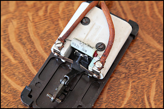
So, having got the top off and picked the button up off the floor, what lays before you will look something like this …
The T-shaped thing at bottom left is what the button sits on, and the white is the porcelain insulation which contains the variable resistance. Coming down from the top of the picture are the two cores of the mains cable, running inside lengths of heat-resistant sleeving to terminate at those screw terminals . From the back, it looks like this …
Note the cylindrical queerthing with the writing on which is connected across the two terminals. That’s a capacitor which was fitted to prevent interference on AM radio and ancient TV sets. If and when it fails, it usually does so by shorting out, and you’ll know if that’s happened because you will have no control over your machine’s motor speed. It’ll run flat out as soon as you switch on. All you need do you to rectify that situation is remove the capacitor, chuck it out, and put your speed controller back together again. Nowadays, the capacitor is surplus. It serves no purpose at all.
If you’re re-wiring the unit, take care to ensure that the wires are going to be neither tight nor unduly slack when you put the top back on, and do make sure you remembered the heat-resistant sleeving. If the original sleeving is unusable, your best bet for a couple of new bits is probably an auto electrician or a TV/radio repair place. If the rubber/plastic cable entry sleeve’s gone the way of most (like this one has), it needs replacing with something or other so that when the case goes back together, the cable is clamped so it has effective strain relief. In the absence of anything else, winding electrical tape round the cable works if you keep it neat – and keep checking that you haven’t made it too fat to fit the slot in the case top moulding.
Incidentally, the best way to put the top back on is to poke the button up through it the right way round (top sloping down towards the end), and hold the top of the button whilst jiggling the top of the case down into place. As long as you keep the button vertical, it’ll drop straight over the lever thingy inside as you push the top down.
There are adjustments you can make to set one of these things up properly, but suffice it to say that if you’re competent to make those adjustments, it’ll be obvious how you do them.
The controller which hides in the base of a knee-lever machine is essentially the same dog with different spots but it’s a pig to work on, and there is a variant called the Sewing Motor Controller 194386 which was used in “convertible” treadle bases. Maybe that’s something for another post sometime …


You must be logged in to post a comment.